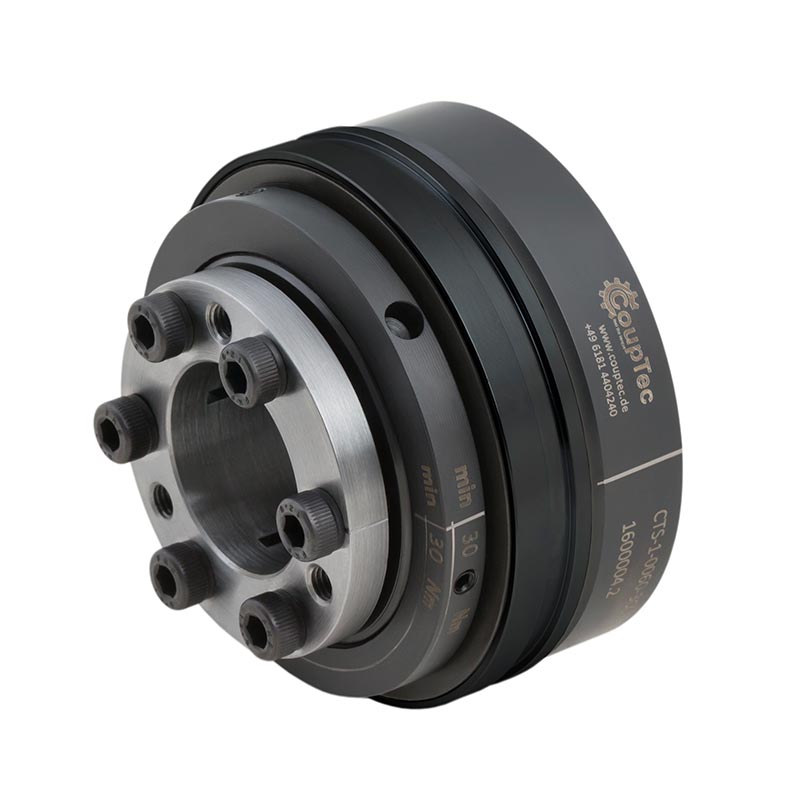
Safety Coupling – Model CTS-1
with clamping ring / conical bushing
- with clamping ring / conical bushing
- 0,2 - 3000 Nm
- exact torque limitation
- torsionally stiff, compact & absolutely backlash-free design
- high switching travel in case of overload
- integrated bearing for toothed belt pulley
- temperature range -30° to 120°
- special designs such as sealed versions or stainless steel on request
| properties | unit | unit symbol | 2 | 5 | 10 | 15 | 30 | 60 | 150 | 200 | 300 | 500 | 800 | 1500 | 2500 |
|---|---|---|---|---|---|---|---|---|---|---|---|---|---|---|---|
| 360°/60° adjustment range 1 from - to | (Nm) | TKN | 0,2-1,5 | 1-5 | 2-6 | 5-20 | 10-30 | 10-30 | 20-70 | 40-100 | 80-200 | 80-200 | 350-650 | 500-900 | 1000-1500 |
| 360°/60° adjustment range 2 from - to | (Nm) | TKN | 0,5-2,2 | 3-10 | 4-12 | 15-40 | 20-60 | 25-80 | 50-150 | 80-200 | 150-250 | 200-400 | 500-800 | 700-1200 | 1400-2200 |
| 360°/60° adjustment range 3 from - to | (Nm) | TKN | 7-15 | 30-60 | 30-90 | 50-100 | 100-225 | 150-280 | 200-440 | 250-500 | 650-950 | 1000-1800 | 2000-3000 | ||
| 360°/60° adjustment range 4 from - to | (Nm) | TKN | 250-400 | 320-650 | |||||||||||
| actuation distance * | (mm) | 0,8 | 0,8 | 1,2 | 1,4 | 1,4 | 1,7 | 1,9 | 2,2 | 2,2 | 2,2 | 2,2 | 3 | 3 | |
| (F) adjustment range 1 from - to | (Nm) | TFKN | -- | -- | 2-5 | 7-15 | 8-20 | 15-30 | 40-80 | 50-100 | 60-180 | 80-150 | 200-400 | 700-1000 | 1000-1500 |
| (F) adjustment range 2 from - to | (Nm) | TFKN | 4-10 | 15-30 | 30-60 | 80-150 | 80-140 | 160-300 | 100-250 | 400-650 | 1000-1250 | 1400-2200 | |||
| (F) adjustment range 3 from - to | (Nm) | TFKN | 8-15 | 130-200 | 280-400 | 150-300 | 450-850 | 1250-1500 | 1800-2700 | ||||||
| (F) adjustment range 4 from - to | (Nm) | TFKN | 250-500 | 2500-3000 | |||||||||||
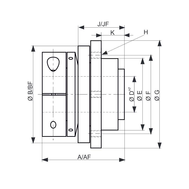
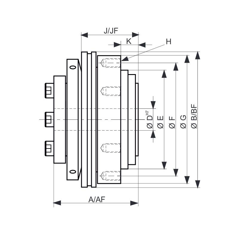
| overall length | (mm) | A | 28 | 32 | 39 | 40 | 50 | 54 | 58 | 63,5 | 70,5 | 84,5 | 95 | 109 | 147 |
| overall length (F) | (mm) | AF | -- | -- | 39 | 40 | 50 | 54 | 58 | 66,5 | 74 | 88 | 95 | 117 | 153 |
| actuation ring Ø | (mm) | B | 30 | 36 | 46 | 56 | 66 | 74 | 93 | 100 | 121,5 | 136 | 153,5 | 175 | 244 |
| actuation ring Ø | BF | -- | -- | 51,5 | 61,5 | 71 | 84 | 99 | 118 | 133 | 156 | 176 | 188 | 259 | |
| inner diameter from Ø-Ø H7 | (mm) | D | 4-12 | 5-14 | 6-20 | 8-22 | 12-22 | 12-30 | 15-38 | 20-44 | 25-56 | 25-56 | 30-60 | 35-70 | 50-100 |
| pilot diameter h7 | (mm) | E | 22 | 25 | 34 | 40 | 47 | 55 | 68 | 75 | 82 | 90 | 100 | 125 | 168 |
| bolt-hole circle Ø ±0,2 | (mm) | F | 28 | 35 | 43 | 47 | 54 | 63 | 78 | 85 | 98 | 110 | 120 | 148 | 202 |
| flange outs. Ø -0,2 | (mm) | G | 32 | 41 | 51 | 54 | 64 | 73 | 88 | 99 | 113 | 129 | 141 | 166 | 241 |
| thread | H | 4xM2,5 | 6xM2,5 | 6xM3 | 6xM4 | 6xM5 | 6xM5 | 6xM6 | 6xM6 | 6xM8 | 6xM8 | 6xM10 | 6xM12 | 6xM16 | |
| thread depth | (mm) | 4 | 4 | 5 | 6 | 9 | 9 | 10 | 11 | 10 | 12 | 18 | 16 | 24 | |
| distance | (mm) | J | 15 | 17 | 22 | 27 | 35 | 37 | 39 | 44 | 47 | 59 | 67 | 82 | 112 |
| distance (F) | JF | -- | -- | 24 | 27 | 37 | 39 | 41,5 | 47 | 51,5 | 62 | 75 | 94 | 120 | |
| distance | (mm) | K | 6 | 8 | 11 | 8 | 11 | 11 | 12 | 12 | 15 | 21 | 19 | 25 | 34 |
| approximate weight | (kg) | 0,06 | 0,12 | 0,2 | 0,4 | 0,7 | 1 | 1,3 | 2 | 3 | 4 | 5,5 | 10 | 28 | |
| CT-S1-23-01 |
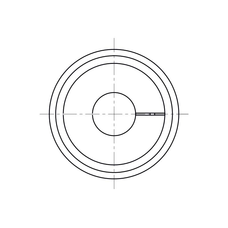
Upper drawing: Series 0002-0010 with clamping ring
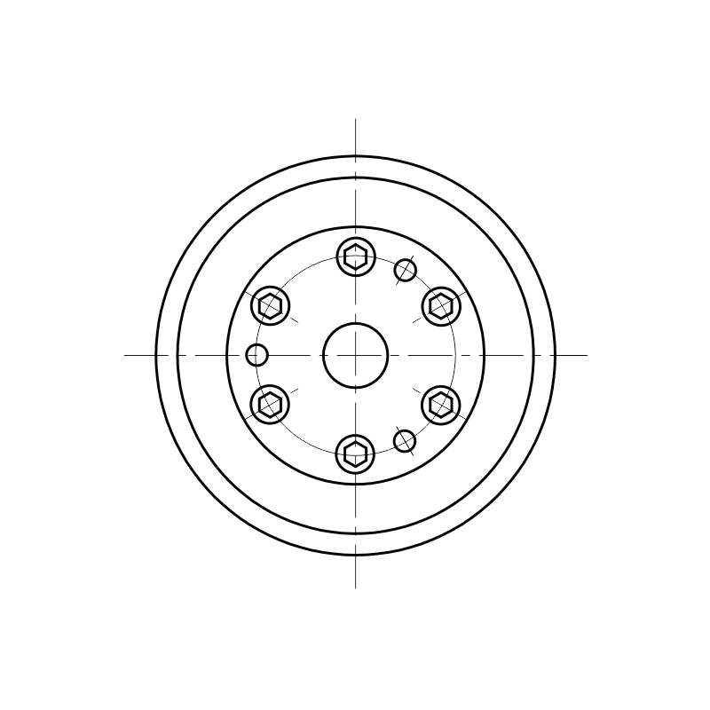
Lower drawing: Series 0015 -2500 with conical bushing
* = Switching distances generally apply to the middle setting range and may slightly deviate downwards or upwards.
