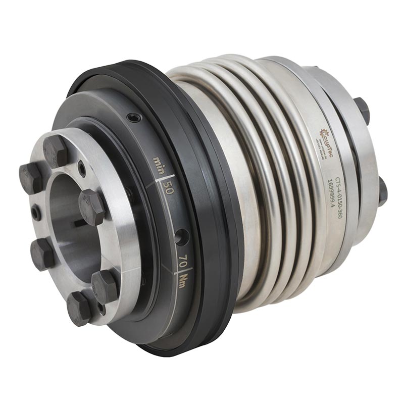
Safety Coupling – Model CTS-4
with conical bushing and metal bellow
- with conical bushing and metal bellow
- 5 - 2.700 Nm
- low moment of inertia
- low residual friction after disengagement
- compensation of shaft misalignment
- infinitely variable torque
- exact torque limitation
- temperature range -30° to 100°
- special designs such as sealed versions, welded versions or stainless steel on request

| properties | unit | unit symbol | 15 | 30 | 60 | 150 | 200 | 300 | 500 | 800 | 1500 | 2500 |
|---|---|---|---|---|---|---|---|---|---|---|---|---|
| 360°/60° adjustment range 1 from - to | (Nm) | TKN | 5-15 | 5-15 | 10-30 | 20-70 | 40-100 | 80-200 | 80-200 | 350-650 | 500-900 | 1000-1500 |
| 360°/60° adjustment range 2 from - to | (Nm) | TKN | 8-20 | 10-30 | 25-80 | 50-150 | 60-160 | 150-250 | 200-400 | 500-800 | 700-1200 | 1400-2200 |
| 360°/60° adjustment range 3 from - to | (Nm) | TKN | 120-240 | 200-320 | 250-500 | 1000-1800 | 2000-2800 | |||||
| 360°/60° adjustment range 4 from - to | (Nm) | TKN | ||||||||||
| actuation distance * | (mm) | 1,4 | 1,4 | 1,7 | 1,9 | 2,2 | 2,2 | 2,2 | 2,2 | 3 | 3 | |
| (F) adjustment range 1 from - to | (Nm) | TFKN | 7-15 | 8-20 | 15-30 | 40-80 | 50-100 | 60-180 | 80-150 | 200-400 | 700-1000 | 1000-1500 |
| (F) adjustment range 2 from - to | (Nm) | TFKN | 15-30 | 30-60 | 80-150 | 80-140 | 160-300 | 100-250 | 400-650 | 1000-1250 | 1400-2200 | |
| (F) adjustment range 3 from - to | (Nm) | TFKN | 130-200 | 150-300 | 450-850 | 1250-1500 | 1800-2700 | |||||
| (F) adjustment range 4 from - to | (Nm) | TFKN | 250-500 | |||||||||
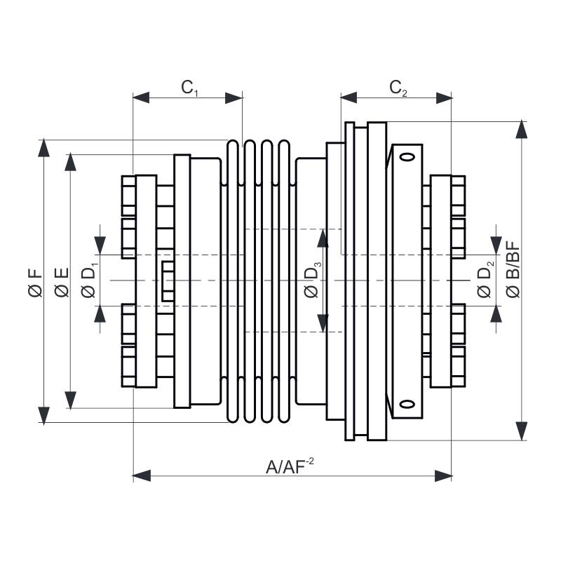
| overall length | (mm) | A-2 | 62 | 69 | 72 | 80 | 83 | 93 | 93 | 105 | 100 | 112 | 115 | 129 | 124 | 138 | 152 | -- | 175 | -- | 250 | -- |
| overall length (F) | AF-2 | 62 | 69 | 72 | 80 | 83 | 93 | 93 | 105 | 103 | 115 | 118 | 132 | 129 | 143 | 154 | -- | 183 | -- | 256 | -- | |
| actuation ring Ø | (mm) | B | 56 | 66 | 74 | 93 | 100 | 121,5 | 136 | 153,5 | 175 | 244 |
| actuation ring (F) Ø | (mm) | BF | 61,5 | 71 | 84 | 99 | 118 | 133 | 156 | 176 | 188 | 259 |
| clamping fit length | (mm) | C1/C2 | 19 | 21,5 | 27,5 | 32 | 32 | 41,5 | 41,5 | 49 | 61 | 80,5 |
| inner diameter from Ø-Ø H7 | (mm) | D1 | 10-22 | 12-23 | 12-29 | 15-37 | 20-44 | 25-56 | 25-60 | 30-60 | 35-70 | 50-100 |
| inner diameter from Ø-Ø H7 | (mm) | D2 | 10-22 | 12-23 | 12-29 | 15-37 | 20-44 | 25-56 | 25-60 | 30-60 | 35-70 | 50-100 |
| diameter | (mm) | E | 44,5 | 50 | 61 | 74 | 83 | 103 | 114 | 116 | 141 | 181 |
| diameter | (mm) | F | 49 | 55 | 66,5 | 81 | 90 | 110 | 123 | 132 | 157 | 199 |
| approximate weight | (kg) | 0,3 | 0,4 | 1,2 | 2,2 | 3 | 5 | 6,5 | 9 | 16 | 34 | |
| CT-S4-24-02 |
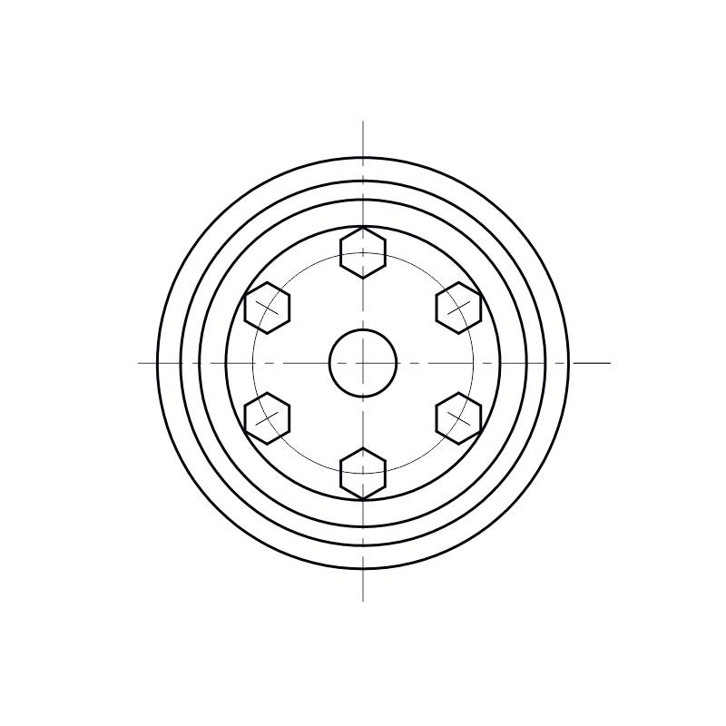
Series 0015-2500 with conical clamping hubs
The actual weight is determined by the size of the fitting (D).
Up to series 300 the couplings are glued, from series 500 they are welded.
* = Switching distances generally apply to the middle setting range and may slightly deviate downwards or upwards.


